Welcome to computing! |
||
|
|
||
| 1. | Check the contents of your VIC
container. You should find the following items: --- VIC 20 Personal Computer --- Power Supply (large box with 2 cords coming out of it) --- RF Modulator (small metal box) and short cable --- Video Cable
|
|
| 2. | You will need two electrical outlets (sockets) ---
one for the VIC and one for your television set.
|
|
| 3. | Position the VIC and television set so you
can use the keyboard comfortably while viewing the television screen...
ideally, a tabletop or desk.
|
|
| 4. | Find the ON/OFF switch on the right hand side of the
VIC. Make sure it's in the "OFF" position. |
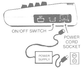 |
| 5. | There are two cords coming out of the power supply box. Plug the power supply cord into an electrical outlet and plug the other cord into the power cord socket on the side of the VIC. (NOTE: The power supply remains "on" while plugged in so you should unplug it when not in use.) | |
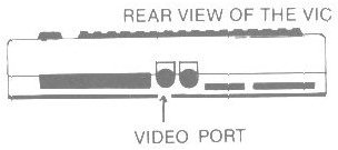
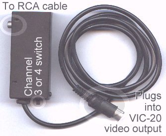
6. |
Connect the video cable to the back of the VIC and to the RF Modulator box, as shown. Make sure to connect it to the video port and not to the 6-pin serial port, which is next to it. |
 |
| Note: You can use a monitor instead of a television set -- in which case you can go directly from the VIC to the monitor cable, without the RF Modulator. (But doing this might require special cables.) | 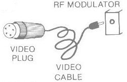 |
|
| 7. | Connect the RF Modulator to your television set. For this you'll need a screwdriver. The short TV connector cord runs from the RF Modulator box to the 2 VHF Antenna leads on the back of your television. Simply connect the two wires to the VHF leads and tighten the screws firmly. | 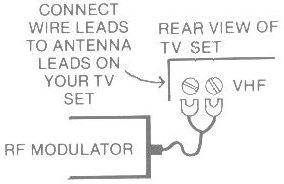 |
Note: Some VICs are provided with a "switchbox" which attaches between the RF modulator and TV set. The switchbox contains a switch with settings for "computer" and "TV" and should be set to "computer" when using the VIC. |
||
8. |
Turn on the TV set. |
|
9. |
Turn on the VIC (the red power light on the top of the computer should come on). If the power light does not, consult the accompanying troubleshooting chart.
|
|
| 10. | There is a switch on the RF Modulator for selecting
either channel 3 or 4. Choose the channel with the weaker
reception in your area, and set both the TV and the Modulator
to that channel. The fine tuning on your television may need
some adjustment.
|
|
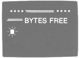
| Here is what you should see on the screen --- sometimes it
takes a second or two to activate. If you don't get the following display on your screen, turn the computer off, wait a few seconds and turn it on again. |
|
|
| 11. | Adjusting the color and tint / hue depends on the
color controls provided on your television set -- naturally, sets
with better controls yeild better color. Some sets show some colors
better than others.
|
|
| 12. | If you have trouble with any
of these steps, consult
the troubleshooting chart.
|
|
NOW... you are ready to start using the VIC. |
||
|
|
||
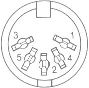
| As a bonus, for any of you tempted to solder
up a monitor cable, here is a pinout diagram for the
video port. (It also came in the owner's manual.)
Pin 1 = 5 volts reg. (10 mA max) |
|
|
|
|
||
And just for comparison purposes, here is the pinout |
||
| Pin 1 = Luminance Pin 2 = Ground Pin 3 = Audio out Pin 4 = Video out Pin 5 = Audio in |
||
|
||